Kelp Is on the Way
Modular System for Optimizing and Modernizing Kelp Aquaculture
Senior Design Project in Mechanical Engineering

W
hat is it?
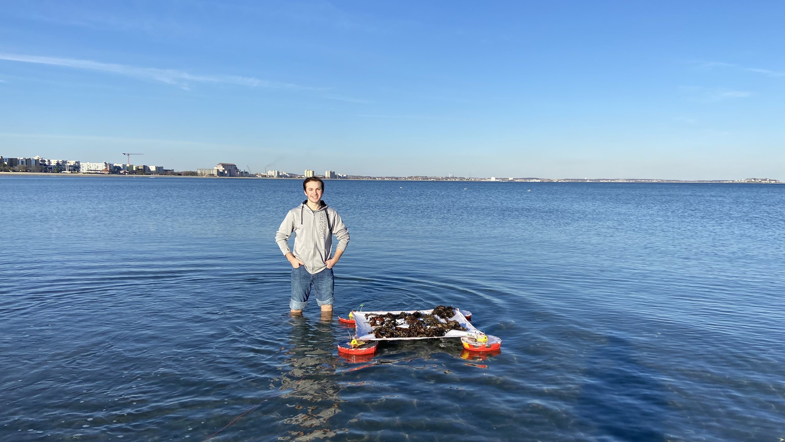
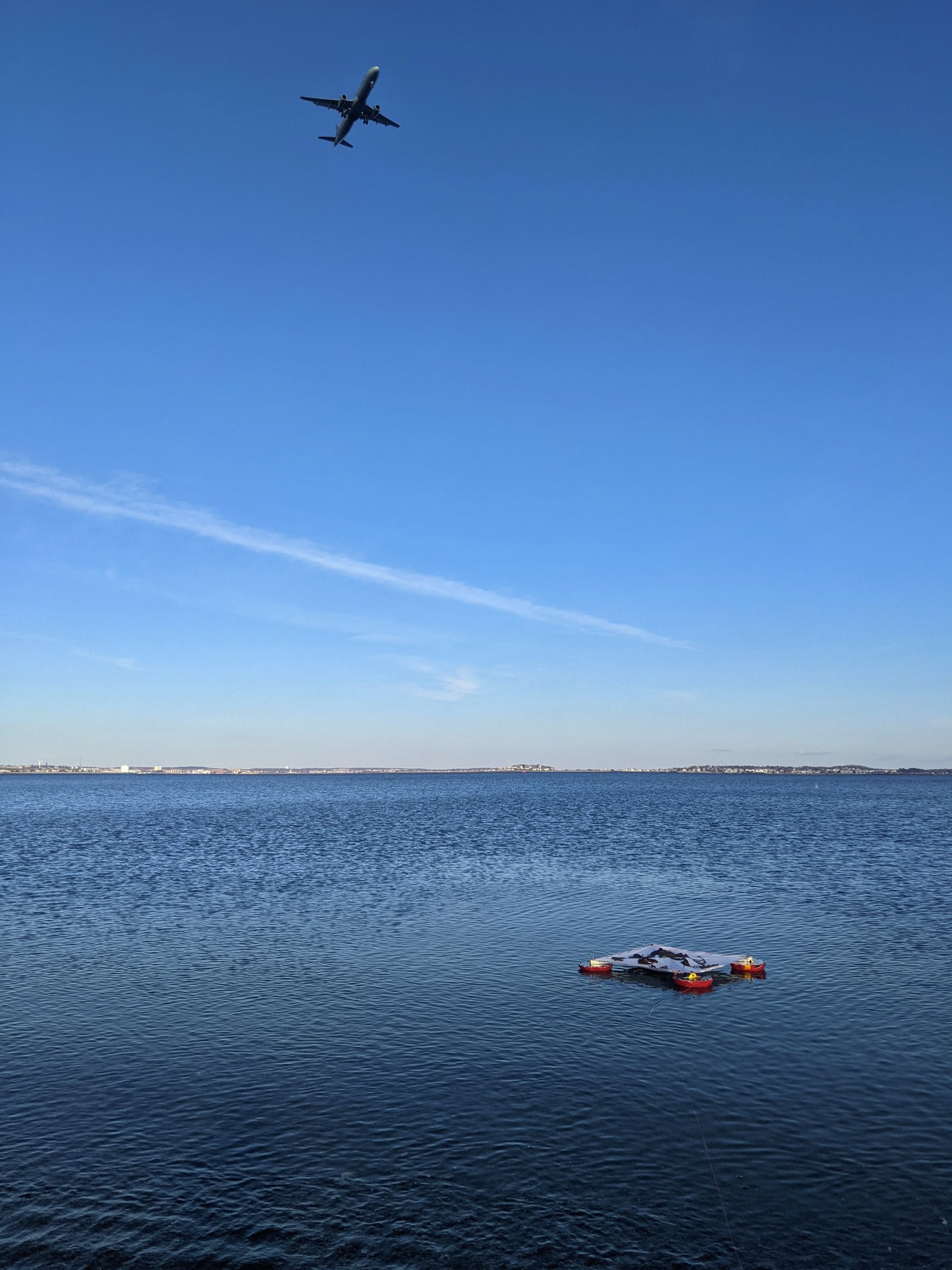
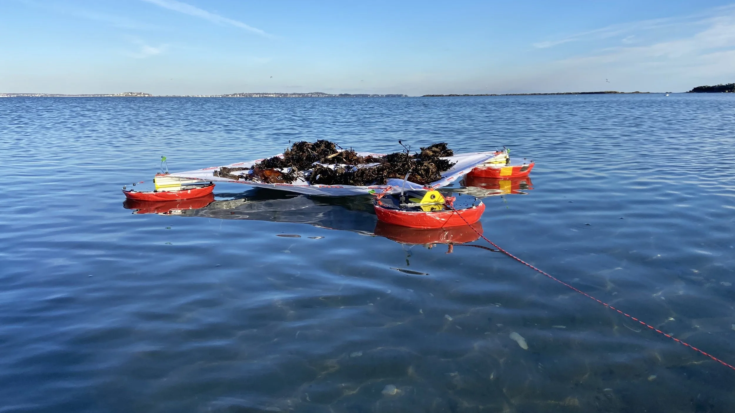
A prototype module for farming kelp in an efficient, modular way.
This is one unit of what would comprise a larger matrix. Together, these square textiles would span whatever area kelp is to be grown within. Seen here floating on the surface of the ocean, each unit would passively rest at a depth of about one meter, neutrally buoyant, while the kelp grows up towards the surface from the inoculated textile. When it comes time to harvest (either triggered by the automated system based on data from onboard sensors or manually, by a farmer), the buoys inflate and the system rises to the surface. As it floats there, sunlight dries the kelp, so it is approximately 90% lighter than wet kelp by the time a ship comes to retrieve it. Because of this massive weight reduction, the retrieval process is far more energy-efficient.
Meet the Kelp Is on the Way Team
-

Teddy Robbins
TEAM MANAGER
-

Auguste Brown
ENVIRONMENTALIST
-

Jeffrey Blitt (me)
FABRICATION SPECIALIST
-

Raymond Rogers
NIGHT SHIFT
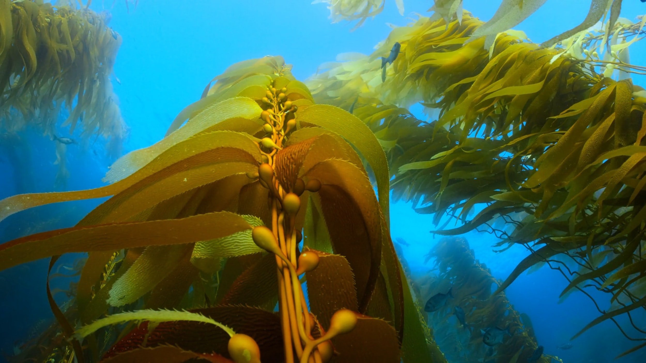
Why Kelp?
There are endless problems in need of mechanical solutions, with many of those within the sustainability space. Our planet needs help—why not kelp?
Brown algae agriculture is environmentally effective, economically attractive, and technologically underdeveloped. Here are just a few uses for kelp:
-
Kelp forests can sequester up to 20 times more carbon than terrestrial forests per unit area.
The carbon absorbed by kelp during its growth makes up about 30% of its dry weight.
-
Kelp is a nutrient-dense food, containing vitamins and minerals that it can be hard to get enough of without supplements.
It can be eaten raw or cooked, and is prepared a myriad of different ways.
-
Kelp is a plentiful source of many compounds which can be used as additives in cosmetics, pharmaceuticals, food products, fertilizers, and many other applications.
-
The fast-growing nature of kelp, as well as its ubiquity, scalability, and high carbohydrate content make it very suitable for use as a biofuel.
There are, however, concerns about the sustainability of biofuels and the rerelease of sequestered carbon.
Some of Our Goals:
-
Automate.
Reduce the active human involvement necessary to farm kelp without sacrificing the benefits of the current methods.
-
Monitor.
Carefully measure and monitor kelp growing conditions to keep farmers aware of what might need fixing or changing.
-
Maintain.
Make improvements to how kelp farming works, but don’t disrupt the format so much that it scares away the stakeholders.
-
Optimize.
Use data to identify optimal harvest times, increasing farm yield and efficiency without wresting control from farmers.
Ideation & Design Selection
We followed the ideation and design steps laid out by our professors:
A framework consisting of three distinct sets of ideas that progressively approach one solution.
Set A
In Set A, there are no bad ideas. It’s a good thing, too, because we thought up some pretty wild concepts at the beginning (see Urch’n Destroy, the sea urchin population control robot). Mindful of the next steps, though, we decided to categorize these ideas into three main groups: Monitoring (what data we’re collecting and how), Actuation (what we’re doing to the farm based on the data), and Data Readout (how we’re presenting that data to the user).
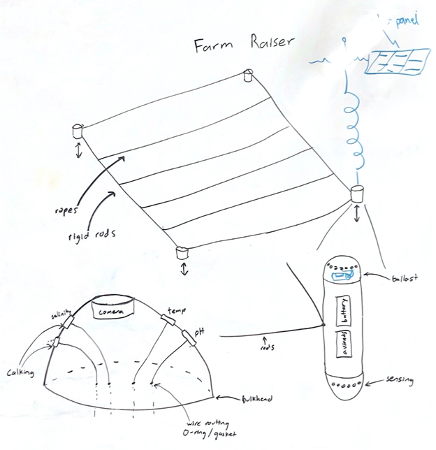
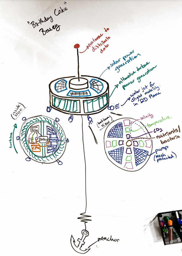
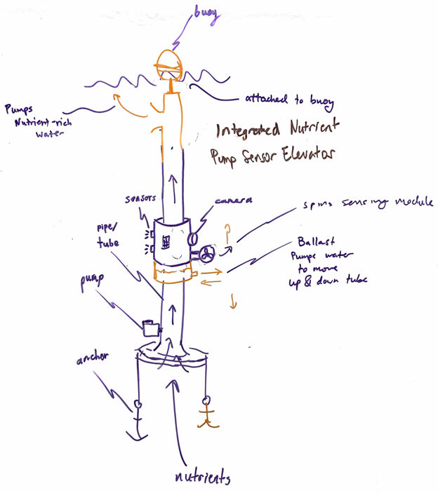
Below, I’ve included a collection of our Set A sketches, created collaboratively by the whole team on the whiteboards in the Nolop makerspace over the course of several days. These are mostly sorted into our three categories, but there was a considerable amount of cross-pollination between the groups.


Note from the future:
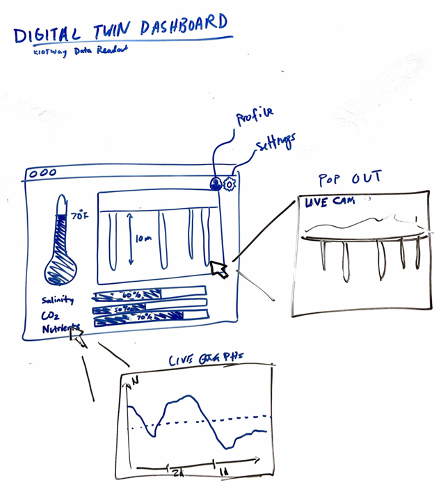
The ideation for monitoring and actuation was intertwined between the two, as each proposed system usually had a subsystem for each of these two purposes combined into one larger design. Contrarily, the ideas for data readout were almost entirely confined to digital dashboards, so they were ideated and discussed more isolated from the other two subsystems, assuming the best candidates from each could eventually be plug-and-play compatible with one another. Eventually, we did make the call to scale back the digital dashboard to be more barebones, as we were afraid of scope creep.
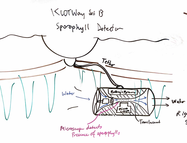
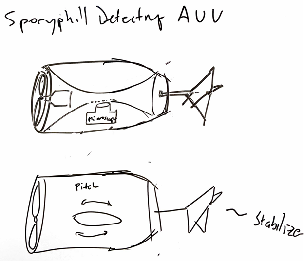
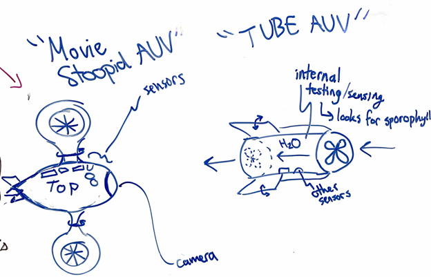
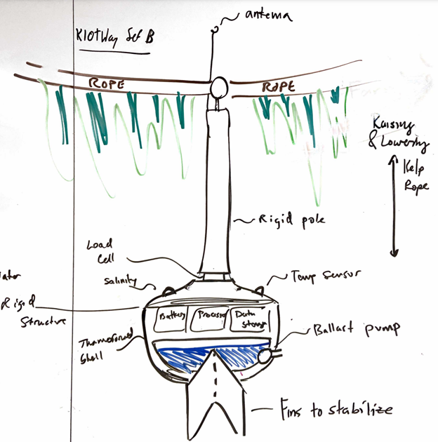
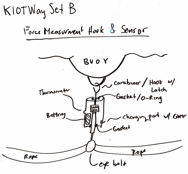
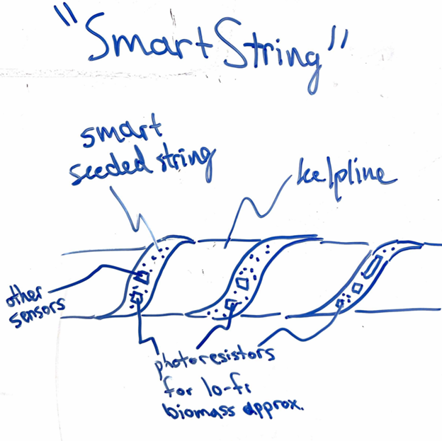
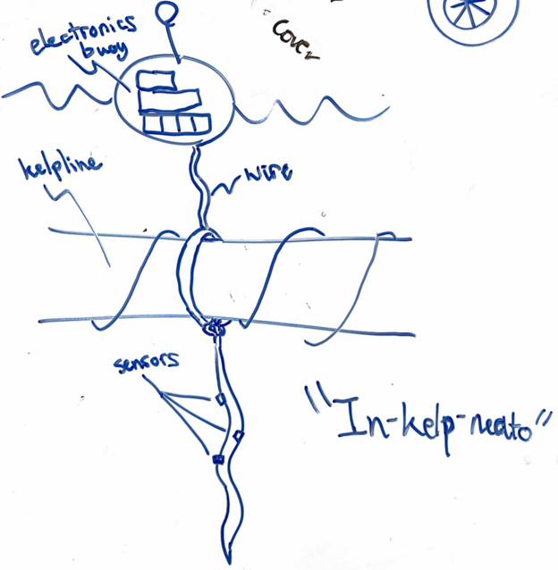
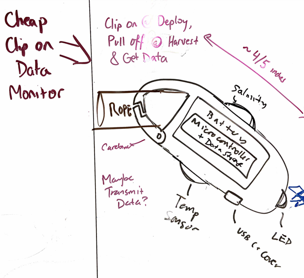
Set B
The ideas in Set B were a cut above Set A. The wackier ideas started to fall away when deemed impractical, and some of the less glamorous ideas started to become frontrunners as their simplicity and feasibility became clearer assets. We combined and improved upon ideas from Set A, with a couple of new concepts thrown into the mix as well. Each solution was still just a thought, but those thoughts started to make sense. Here are some scans of our Set B sketches:

Set C
Set C was really when our ideas turned into design concepts. Each of the items in our Set C was a proposed solution that beat out other ideas through Pugh chart comparison and other means of differentiation. We settled on four ideas, one for each of our group members to flesh out and draw up in CAD. These designs, while still short of being ready for a job shop, were in-depth enough to illustrate many strengths and weaknesses, including manufacturability, affordability, and feasibility within our limited timeframe. See below for a brief view of each Set C design.
Smart Buoy (Ray)
Clip-on Sensor Suite (Teddy)
Textile Matrix (Gus)
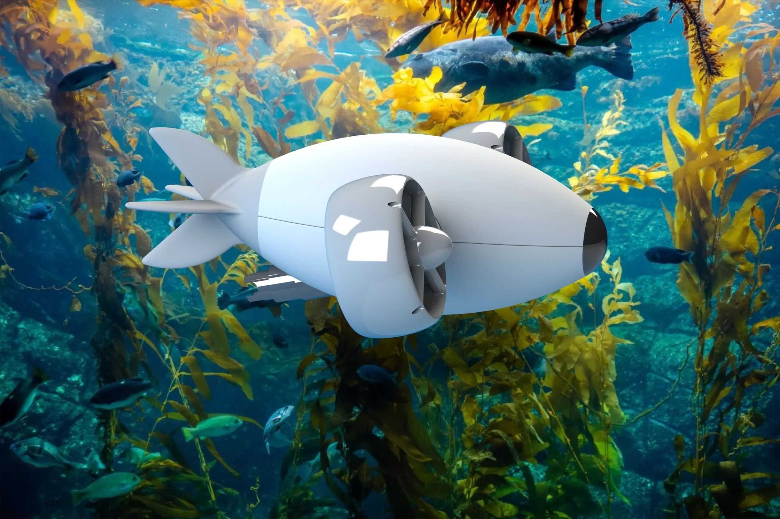
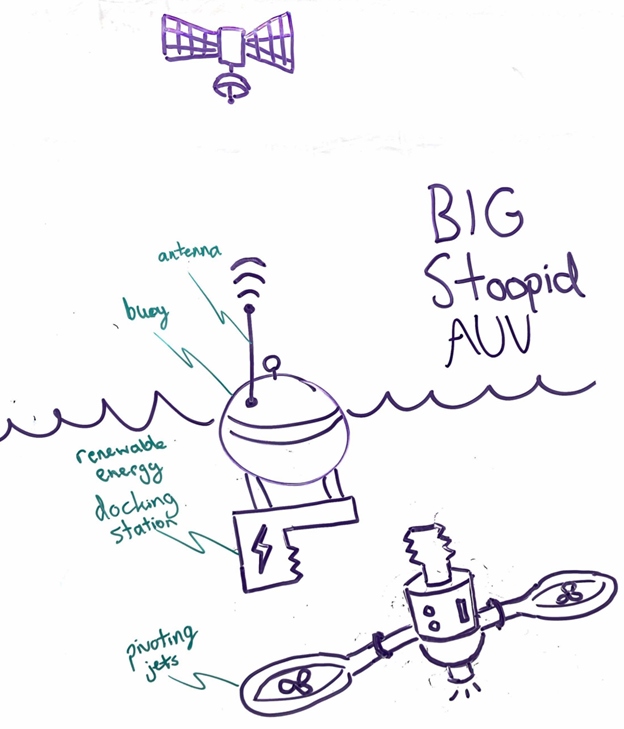
Autonomous Underwater Vehicle (me)
Choosing Our Final Design
Ultimately, we opted for a modified version of the “Textile Matrix” design which uses flexible bladder buoys inflated and deflated from a central hub instead of rigid buoys with active ballast systems onboard. This allowed for all the perks of the original textile matrix design with the added bonus of reduced complexity and the ability to use an onboard compressed air tank rather than trying to pump air down from the surface.

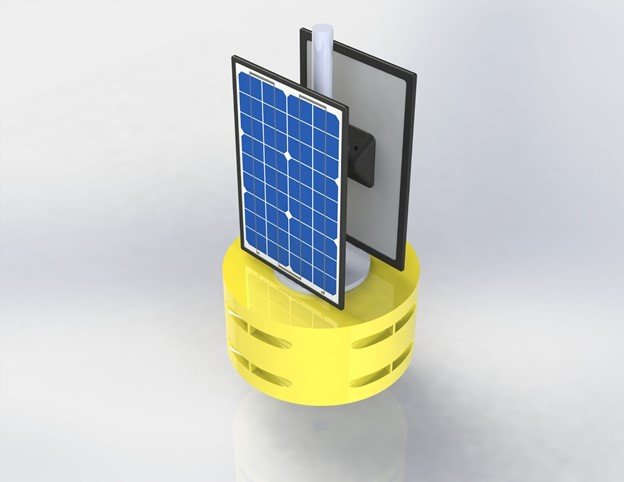
Modified Textile Matrix
This is a sketch of the final design with a closeup on a buoy.
At the top of the drawing, the surface buoy is shown. Though it was outside our scope to build, it is an important aspect of the design. Were the system to be implemented for real with more than one textile unit, a group of units could theoretically be run off the power generated by the solar panel array on a single buoy. Additionally, this buoy would be the center of a hub-and-spoke network with the textile units and would allow for long-range radio communication to occur, liaising between the sensors and the internet.
Prototype Construction
A Step-by-step Guide to Our Physical Build Process
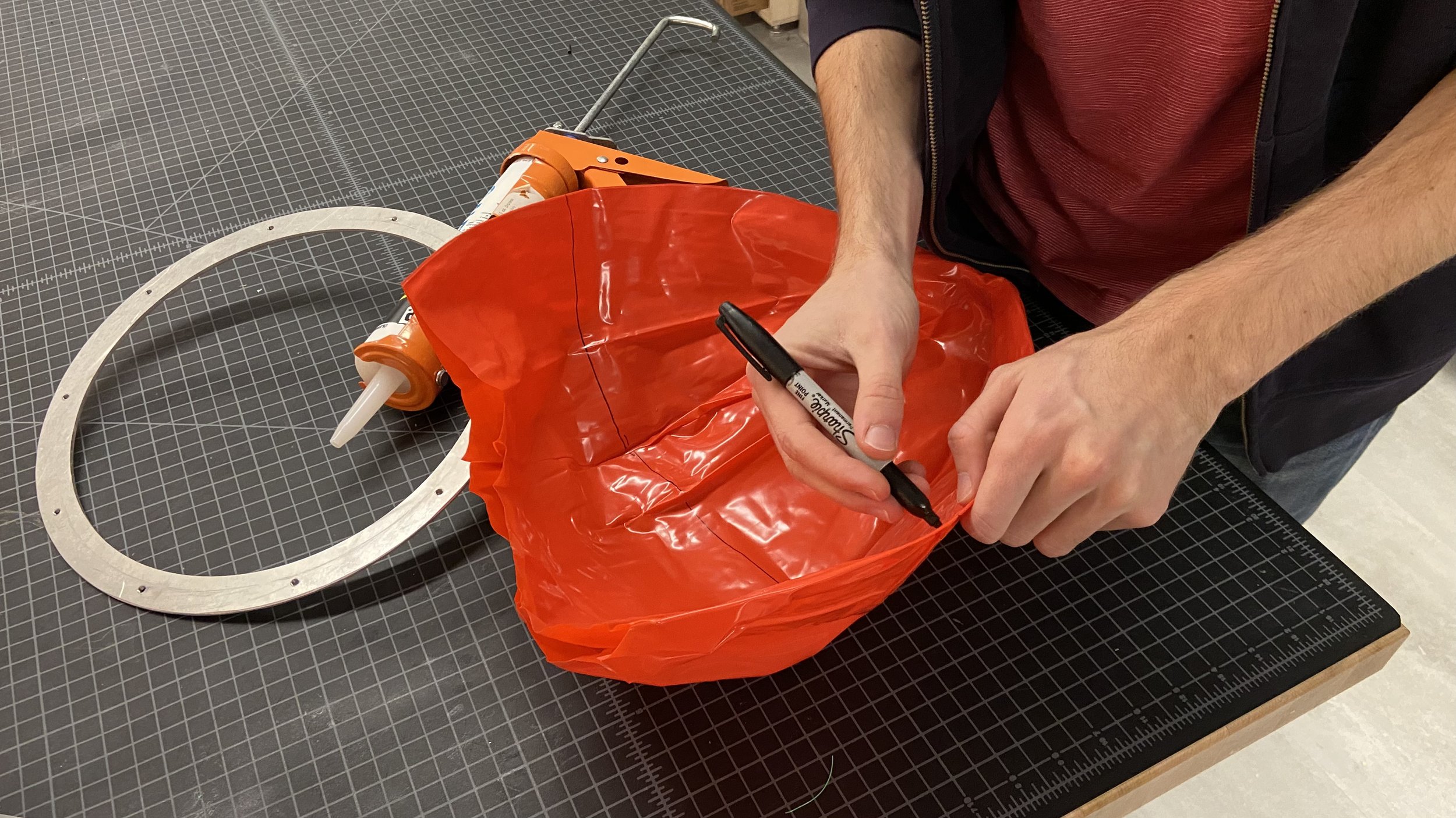
To make each buoy, we started by cutting about the top third off a beach ball, then we wrapped the open side over a waterjet-cut aluminum ring.

We then pressed the cut edge between the aluminum ring and a laser-cut acrylic mounting plate, securing the connection with machine screws and sealing it with waterproof silicone caulk.

Tubing is attached to each buoy via an airtight cable gland, then each buoy is preliminarily inflated and leak-tested.
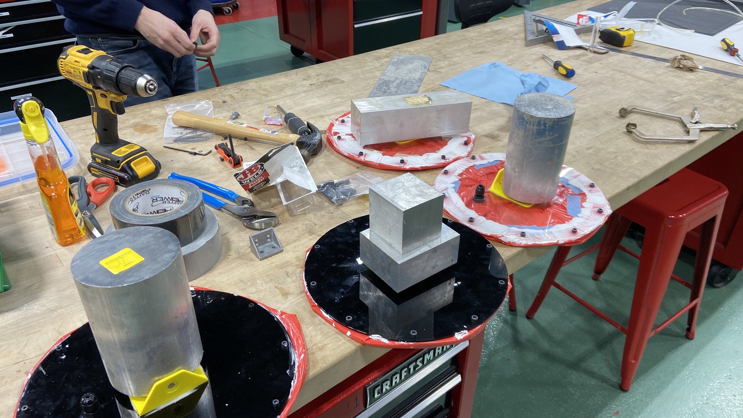
Next, we epoxied 3D-printed mounting brackets to the tops of the buoy plates, which have been roughed up for better adhesion.

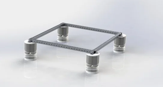
When it comes time to attach the buoys to the frame, the brackets slide onto the extrusion and can be secured with a machine screw.

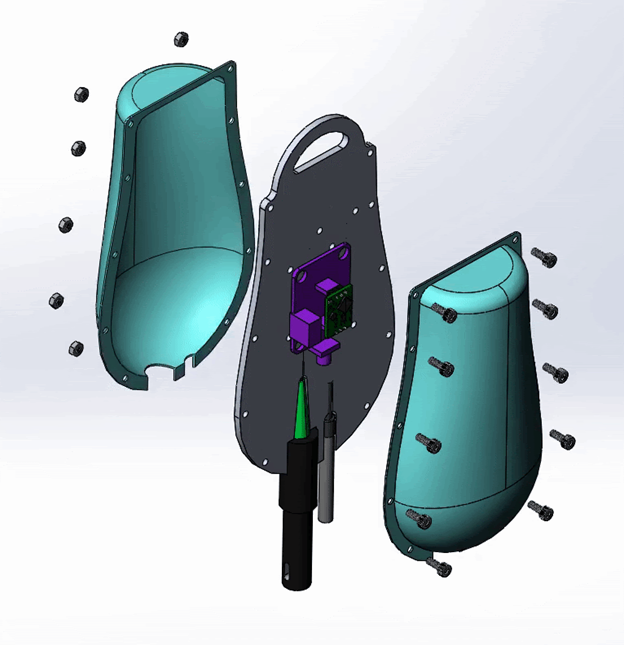
We purchased a waterproof plastic bin for the electronics to sit within. We then 3D-printed another mounting bracket, epoxied it to the top of the bin, and secured a waterjet-cut plate to that bracket, which can in turn be attached to the aluminum extrusion to form the frame.

Once the frame has been assembled, a piece of thick fabric is cut to size and holes are poked around the perimeter. A length of paracord is woven through these holes and secured at each corner of the frame, then tensioned to secure the textile.

The buoys are then attached and the pneumatics system is connected.

The electronics and pneumatics are mounted to an acrylic plate and secured to the bin.

At this point, the unit should be fully assembled. Time to farm some kelp!
Pneumatics
Powerful & Dangerous

Initially, we planned to control the ballast system on our farm modules using a system of pumps. One major hurdle presented by this approach is that the air supply needs to come from somewhere, so without a tank to draw from, we would have needed to devise a system leading air intake hoses down from the surface. When we considered the pressures at play and the dangers of seawater or rainwater flooding the air supply hoses, we quickly realized this idea was infeasible.
Instead, we opted for compressed air. After all, wouldn't it be better for our system to be self-contained than for it to rely on drawing air from the surface environment? Well, as it turns out, pneumatics can be quite complicated, and that question may not be as rhetorical as we initially thought. Our first major mistake was not the choice to use compressed air, though; it was the trivialization of the pressure in our compressed air tank.
“Surely, getting more air for the same price is a better idea.”
We thought that was sound logic: more product at the same price point is very appealing when you’re working on a limited budget. Unfortunately, we overlooked a crucial detail in our product selection—while SodaStream refill canisters are a great bang for your buck, the “60L” designation on the side of the packaging is not an indication of the volume of gas in the canister at STP. Rather, a 60L refill contains enough carbon dioxide for users to carbonate 60L of beverages (about 223L). Worse still, even if the canisters had contained that amount, they still would have been pressurized to nearly 900 psi. It was only after our first accident that we learned this was an order of magnitude above the working pressures of standard pneumatic systems—and that the true pressure was around 3300 psi.
Throughout the duration of our project, we experienced two real scares, both stemming from our choice to use this high-pressure compressed CO2. The first pneumatics accident was a lot scarier, in my opinion, than the second. At that point, we were still blissfully unaware that we’d created a dangerous high-power system, so it had the element of surprise.
For context, we needed to use a series of adapters in order to make the SodaStream canister compatible with our other pneumatic components, but the stock adapters could only take us so far. With all the fittings connected, the canister could not yet fill the system with air. The openings of the canisters have built-in valves which require downwards pressure aimed into the tank to enable flow, so using this compressed air within our system required a custom adapter on our end. I designed and printed a small disc-shaped part with radial cutouts and a protruding central nub, and it worked like a charm. With this button key inserted and all the fittings tightened down, the system would be pressurized and, in theory, ready to go.
One major flaw in this plan was that we had not included a shutoff valve, so as soon as the canister was screwed in, the whole system was pressurized. Another major flaw was that we had not even considered the use of a pressure regulator, so the entire system was subjected to over 3000 psi.


Bottom of button key part, before (left) and after (right) use at high pressure

Top of button key part, before (left) and after (right) use at high pressure
When we performed our first test of this system, I brazenly screwed together the fittings. There was a plume of ice-cold CO2, two loud pops, and a room full of panicked faces. My hands were freezing, but I unscrewed the system as quickly as possible to disengage the button key and close the canister. Each pop was a failure within the system, but that was unsurprising once we learned our true operating pressure. One pop was a quick-connect gasket blowing right through the fitting, and the other was a hole bursting open in the tubing. We were all unharmed, but the noises were quite loud so our ears were ringing and we were all left in a state of shock.

After that day, we started storing the pneumatics subsystem in a padded pelican case, tucked away in the corner of the Nolop red zone.
With the whole system pressurized, we didn’t want to take any chances.
Then, there was the second incident…
We caught this one on video. It’s hard to tell what’s going on in the clip because it all happens so fast, but I’ll break it down for you:
Essentially, we wanted to detach the canister from the rest of the pneumatics subsystem before attaching it to the rest of the system and assembling the whole project in earnest. At this point, we had added a regulator and a shutoff valve to the system, so we were able to maintain some level of control. Unfortunately, these components both added mass to the system and introduced new cavities which could become pressurized. When I unscrewed the canister from the fittings, the adapters and regulator launched off the tank, striking first my arm, then the wall, then the ceiling, and finally, the floor. Roughly estimated at about 35 m/s (80 mph) using the video, that hunk of brass was traveling fast. We were lucky nobody got seriously hurt.

Even after taking more precautions, it was clear that our system was dangerous. At this point, we stopped, considered what was important, and ultimately decided to scale back our system. We emptied the remaining CO2 from the SodaStream canisters and instead used a small air compressor for our remaining testing and demonstrations.
Key Takeaways
-

Know Your Pneumatics.
Working with highly pressurized gasses is a dangerous endeavor. It’s best practice to include all relevant safety features and think through how your actions will affect and be affected by all parts of the system before making any changes.
-

Balance Your Budget.
When you’re working on a limited budget, it’s important to plan ahead. Sometimes it’s possible to use recycled materials, which is a best-case scenario. When it comes to safety, though, make sure you leave enough funds for what you need.
-

Define Your Scope.
There is always more to add to a project. In order to best accomplish your goals, it’s imperative to focus on what’s most important. We found ourselves at an impasse halfway through the semester, but we made great progress once we clarified our scope.
Some of My Contributions
We all put a lot of time into this project, and I worked varying amounts on each different subsystem. One part to which I contributed a lot was the textile, which I sourced, cut, perforated, threaded, secured, and tensioned. I also did a lot of the hands-on testing, which was probably the most dangerous part of the project. Another role I took on was team driver—as the only one who drives a minivan, it was only natural that I go pick up our materials and bring everyone to the beach for testing. I also did some CAD work, buoy construction, and part sourcing, plus I spent a lot of time doing ideation sketches. Despite all I did for the project, I recognize that some of my teammates did more, and I thank them for that.
Summary Video
Overview video made by Teddy Robbins.
Special Thanks to:
My other team members (Teddy, Gus, Ray, and Renée)
Our advisor, Bryony DuPont
Our other professor, Chris Rogers
Nicole Batrouny and the other Bray Lab staff
Brandon Stafford and the Nolop FAST Facility